Logic Gates
Logic gates carry out basic logical functions and are the basic building structure of digital integrated circuits.
Most of the logic gates take an input of two binary values i.e. 1 or 0. Few circuits may have only some logic gates, while other like microprocessors may have many of them.
In the following examples, Each computer circuit excepts the NOT gate has two inputs, A and B, which might either be 1 (True) or 0 (False). The resulting output could be a single value such as 1 if the result is true or 0 if the result is false.

There are seven differing kinds of logic gates, which are highlighted below.
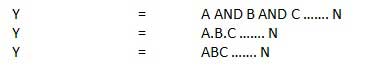
1) AND - True if A and B both inputs are true.
2) OR - True if either A or B is true.
3) NOT - It Inverts the value like True if input is False and False if input is true.
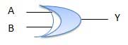
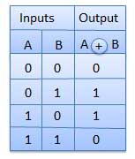
4) XOR - True if either A or B is true, But False if both are true.
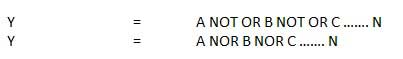
5) NAND - AND followed by NOT i.e. False as long as A and B both are true.
6) NOR - OR followed by NOT i.e. True if A and B both are False.
7) XNOR - XOR followed by NOT i.e. True if A and B both are true or false.
By merging thousands of logic gates, It's possible to carry out highly complex operations. The most number of logic gates on an computer circuit is decided by the dimensions of the chip divided by the scale of the logic gates. Transistors built up most of the logic gates in the computer processors, Smaller transistors mean more complex and faster processors.
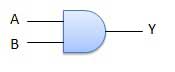
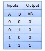
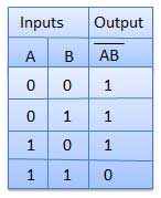
AND Gate
- A logic circuit which carry out an AND operation is shown in figure.
- Physical realization of logical multiplication (AND) operation. Generates an signal of 1 providing all input signals also are 1.
AND gate - Generates an output message as 1 only if all input signals are also 1.
Logic diagram
Truth Table
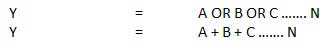
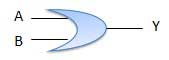
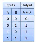
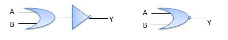
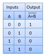
OR Gate -
- A logic circuit which carry out an OR operation is shown in figure.
- Physical realization of logical addition (OR) operation.
- Generates an signal of 1 if a minimum of one in every of the input signals is additionally 1.
Logic diagram
Truth Table
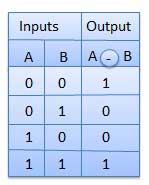
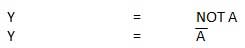
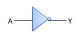
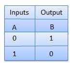
NOT Gate -
- NOT gate is additionally called Inverter. it's one input A and one output Y.
- Physical realization of complementation operation.
- Generates an signal, which is that the reverse of the signal
Logic Diagram
Truth Table
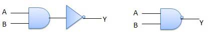
NAND Gate -
- A NOT-AND operation is understood as NAND operation.
- Complemented AND gate.
- Generates an sign of :
- 1 if anyone of the inputs is 0.
- 0 when all the inputs are 1.
Logic Diagram
Truth Table
NOR Gate -
- A NOT-OR operation is thought as NOR operation.
- Complemented OR circuit.
- Generates an output of :
- 1 only if all inputs are 0.
- 0 if anyone of inputs may be a 1.
Logic diagram
Truth Table
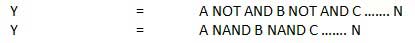
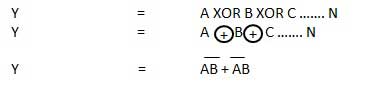
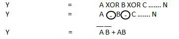
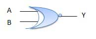
XOR Gate
XOR or Ex-OR gate may be a special sort of gate. It will be utilized in the half adder, full adder and subtractor. The exclusive-OR gate is condensed as EX-OR gate or sometime as X-OR gate.
Logic diagram
Truth Table
XNOR Gate -
XNOR gate could be a special style of gate. It are often employed in the half adder, full adder and subtractor. The exclusive-NOR gate is condensed as EX-NOR gate or sometime as X-NOR gate.
Logic Diagram
Truth Table